Resilient Metal Seals
Resilient metal seals from GFD have already proven themselves worldwide under the most diverse extreme operating conditions. They are used when conventional sealing products can no longer meet the parameters and requirements in new or existing applications.
For example, when the conventional seal is not suitable for the temperature range or the flat gasket cannot compensate for flange gaping or the required leakage rate cannot be achieved by the seal previously used.
Possible applications and advantages:
- Seal for vacuum, gases and liquids under extreme operating conditions.
- Applicable in pressure ranges from UHV up to 5000bar at service temperatures from -269°C to 750°C.
- Resistant against radioactive radiation, chlorides, corrosion and other aggressive influences. No aging.
- Can be optimally adjusted to parameters and requirements in the application through a variety of possible combinations
- Achievement of lowest leakage rates through additional coating
- Maintenance of tightness even when the flange is lifted off by elastic compensation behaviour of the seal
- Resistant to explosive decompression
- Simple force calculations, since ring works in force shunt.
General technical information, applications and industries
Resilient metal seals
Resilient metal seals from GFD are available in a variety of different types, cross sections, wall thicknesses, materials, coatings, coating thicknesses and heat treatments.
Diameters can be defined by the customer starting with the minimum diameters, which depend on the seal type and cross section. Due to the resulting infinite combination possibilities, these sealing elements are manufactured by GFD order-related. For the selection of the most suitable sealing element for your application you are free to contact the technical support of GFD. Please let us know the relevant parameters, e.g. temperature, pressure, medium, surface quality, etc., as well as the requirements in the application, e.g. required leakage rate, load cycles, expected flange lift-off, etc.
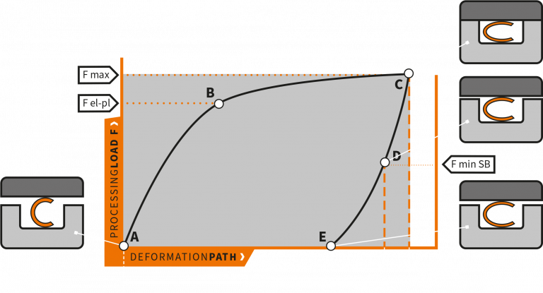
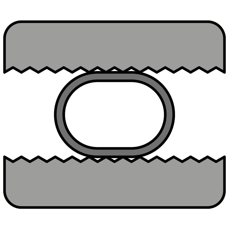
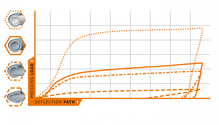
By pressing the sealing element from the original cross section (A) to the required groove depth (C), the maximum press load (F max) is generated. In this process, the ring is not only deformed elastically (A-B) but also plastically (B-C). In the case of coated rings, the press load also causes the coating to flow. Microscopically small irregularities in the counter sealing surface of the groove are closed by this mechanism and the lowest possible leakage rates are ensured. Resilient metal seals have the ability to spring back in a defined manner (C-E) when relieved of load, this behavior is also known as Springback SB. The usable elastic springback (C-D) ensures that the tightness is maintained when flange lift-off occurs as a result of pressure and temperature application. In order to maintain the sealing performance, usually only a part of the total SB can be used, so that the sealing load F min SB is not undercut.
Typical applications / industries
- Machine and plant constructions:
Gas turbines, heat exchangers, plastic injection machines, pressure vessels, pump housings, internal combustion engines - Oil and gas industry:
Fittings, valves, cryogenic applications - Chemical and process technology:
High vacuum, heat exchangers, pressure vessels, fittings, valves, cryogenic applications - Sealing Technology
- Laser and sensor technology
- Aerospace industry:
mechanics, modules, fuel system, engines
Design recommendations
Installation recommendations
Materials
Ring and spring material
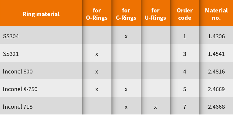
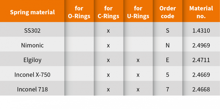
Various stainless steels and nickel alloys are available for the production of rings and springs. The selection of the most suitable material depends on the application and specification.
Heat treatment
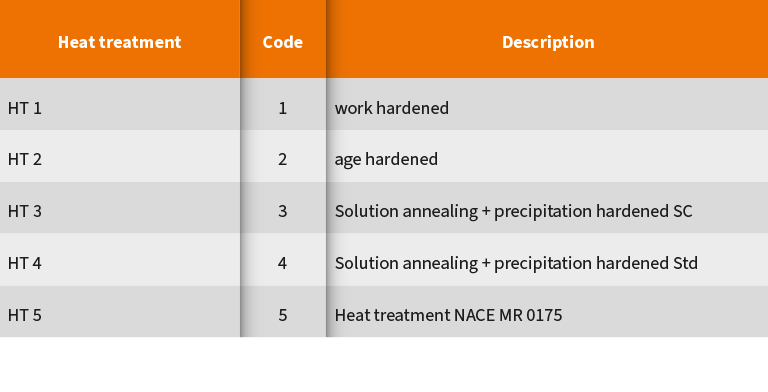
It is possible to subject rings to different heat treatments depending on the materials and applications. A suitable heat treatment can positively influence the performance as well as the lifetime of the rings. The specification can be determined directly by the customer or by GFD if all essential parameters and requirements are present.
Coating materials
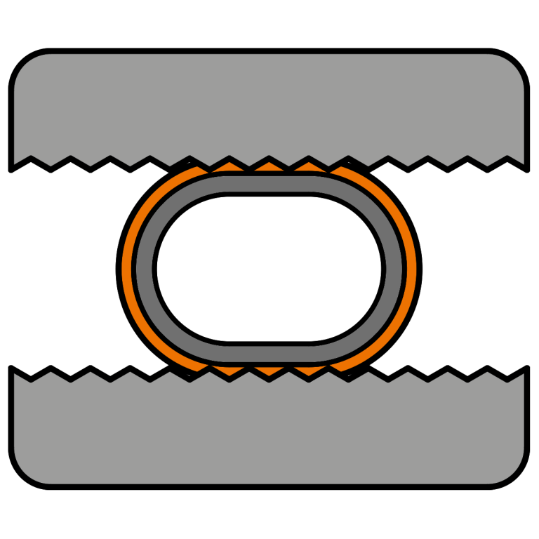
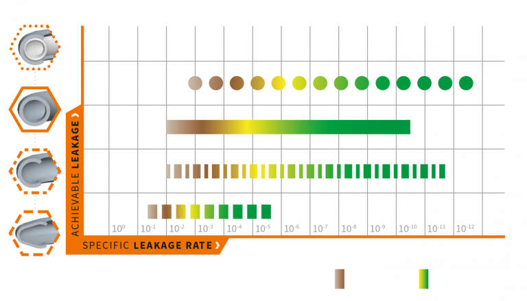
The tightness of metal rings can be significantly improved with a suitable coating: When the ring is pressed, the coating flows into the microscopic unevenness of the counter sealing surface and seals it. This mechanism allows excellent sealing qualities to be achieved. The tightness specified as the leakage rate in mbar l/s is the result of the successful interaction between the ring and the surface quality of the mating sealing surface (see also chapter "Design recommendations and assembly"). The necessity of a coating and, if necessary, the determination of the coating thickness is thus dependent on the desired leakage rate and is further determined by the surface quality of the groove and flange. When selecting the coating, it is important to ensure that it harmonizes with the pressing load of the ring, so that tiling takes place reliably. Thus, a comparatively hard nickel coating should only be used in combination with a ring with high pressing load. In contrast, tin or PTFE coatings should preferably be configured with rings of low pressing force. Silver covers the widest range of applications and is therefore considered the standard coating material. Furthermore, coatings such as PTFE or gold can also be used as protection to improve the resistance against aggressive media.
Overview, functional principle, properties and performance
| Metal O-Ring normal |
Metal O-Ring self energizing |
Metal O-Ring pressure filled |
Metal C-Ring | Metal C-Ring spring energized |
Metal C-Ring Highflex spring energized |
Metal C-Ring for axial pressure |
Metal C-Ring for axial pressure spring energized |
Metal U-Ring | |
|---|---|---|---|---|---|---|---|---|---|
| Internal pressure | 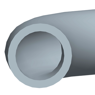 Type MOR Type MORDesign NP |
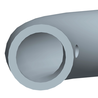 Type MOR Type MORDesign SI |
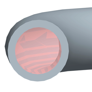 Type MOR Type MORDesign PF |
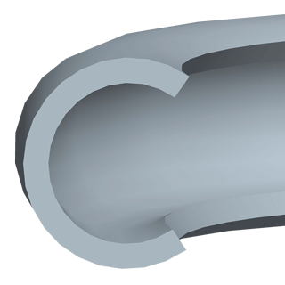 Type MCI Type MCI |
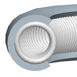 Type MCI-F Type MCI-F |
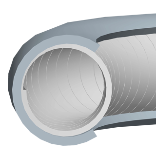 Type MCI-HF Type MCI-HF |
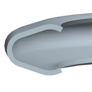 Type MUI Type MUI |
||
| External pressure |  Type MOR Type MORDesign NP |
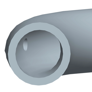 Type MOR Type MORDesign SO |
 Type MOR Type MORDesign PF |
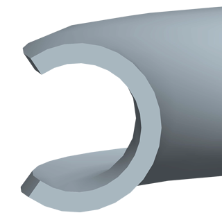 Type MCO Type MCO |
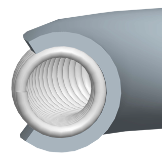 Type MCO-F Type MCO-F |
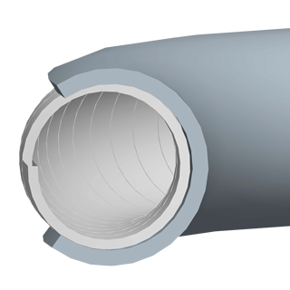 Type MCO-HF Type MCO-HF |
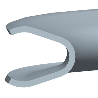 Type MUO Type MUO |
||
| Axial pressure | 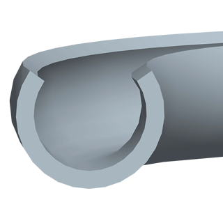 Type MCA Type MCA |
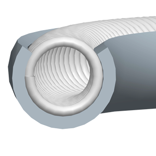 Type MCA-F Type MCA-F |
|||||||
| Description | for low to moderate pressure and vacuum conditions | has a self energizing effect by a drilling hole at the ID or AD | Pressure filling is effective from temperatures of approx. 425°C | Metal C-rings have a higher elasticity than metal O-rings. The open side of the metal C-ring points in the direction of the higher pressure. It therefore has a self energizing effect. The spring reinforcement further improves the sealing effect and springback. | has high springback with low pressing load | ||||
| available as moulded seal | x | x | x | x | x | x | |||
| available as segment seal | x | x | x | x | x | ||||
| Metal O-Ring normal |
||
|---|---|---|
| Internal pressure | External pressure | Axial pressure |
 Type MOR Type MORDesign NP |
 Type MOR Type MORDesign NP |
|
| available as moulded seal | available as moulded seal | |
| available as segment seal | available as segment seal | |
| for low to moderate pressure and vacuum conditions | ||
| Metal O-Ring self energizing |
||
| Internal pressure | External pressure | Axial pressure |
 Type MOR Type MORDesign SI |
 Type MOR Type MORDesign SO |
|
| available as moulded seal | available as moulded seal | |
| available as segment seal | available as segment seal | |
| has a self energizing effect by a drilling hole at the ID or AD | ||
| Metal O-Ring pressure filled |
||
| Internal pressure | External pressure | Axial pressure |
 Type MOR Type MORDesign NP |
 Type MOR Type MORDesign NP |
|
| available as moulded seal | available as moulded seal | |
| Pressure filling is effective from temperatures of approx. 425°C | ||
| Metal C-Ring | ||
| Internal pressure | External pressure | Axial pressure |
 Type MCI Type MCI |
 Type MCO Type MCO |
|
| available as moulded seal | available as moulded seal | |
| available as segment seal | available as segment seal | |
| Metal C-rings have a higher elasticity than metal O-rings. The open side of the metal C-ring points in the direction of the higher pressure. It therefore has a self energizing effect. The spring reinforcement further improves the sealing effect and springback. | ||
| Metal C-Ring spring energized |
||
| Internal pressure | External pressure | Axial pressure |
 Type MCI-F Type MCI-F |
 Type MCO-F Type MCO-F |
|
| available as moulded seal | available as moulded seal | |
| available as segment seal | available as segment seal | |
| Metal C-rings have a higher elasticity than metal O-rings. The open side of the metal C-ring points in the direction of the higher pressure. It therefore has a self energizing effect. The spring reinforcement further improves the sealing effect and springback. | ||
| Metal C-Ring Highflex spring energized |
||
| Internal pressure | External pressure | Axial pressure |
 Type MCI-HF Type MCI-HF |
 Type MCO-HF Type MCO-HF |
|
| available as moulded seal | available as moulded seal | |
| available as segment seal | available as segment seal | |
| Metal C-rings have a higher elasticity than metal O-rings. The open side of the metal C-ring points in the direction of the higher pressure. It therefore has a self energizing effect. The spring reinforcement further improves the sealing effect and springback. | ||
| Metal C-Ring for axial pressure |
||
| Internal pressure | External pressure | Axial pressure |
 Type MCA Type MCA |
||
| Metal C-rings have a higher elasticity than metal O-rings. The open side of the metal C-ring points in the direction of the higher pressure. It therefore has a self energizing effect. The spring reinforcement further improves the sealing effect and springback. | ||
| Metal C-Ring for axial pressure spring energized |
||
| Internal pressure | External pressure | Axial pressure |
 Type MCA-F Type MCA-F |
||
| Metal C-rings have a higher elasticity than metal O-rings. The open side of the metal C-ring points in the direction of the higher pressure. It therefore has a self energizing effect. The spring reinforcement further improves the sealing effect and springback. | ||
| Metal U-Ring | ||
| Internal pressure | External pressure | Axial pressure |
 Type MUI Type MUI |
 Type MUO Type MUO |
|
| has high springback with low pressing load | ||
Metal O-Rings
Internal pressure application
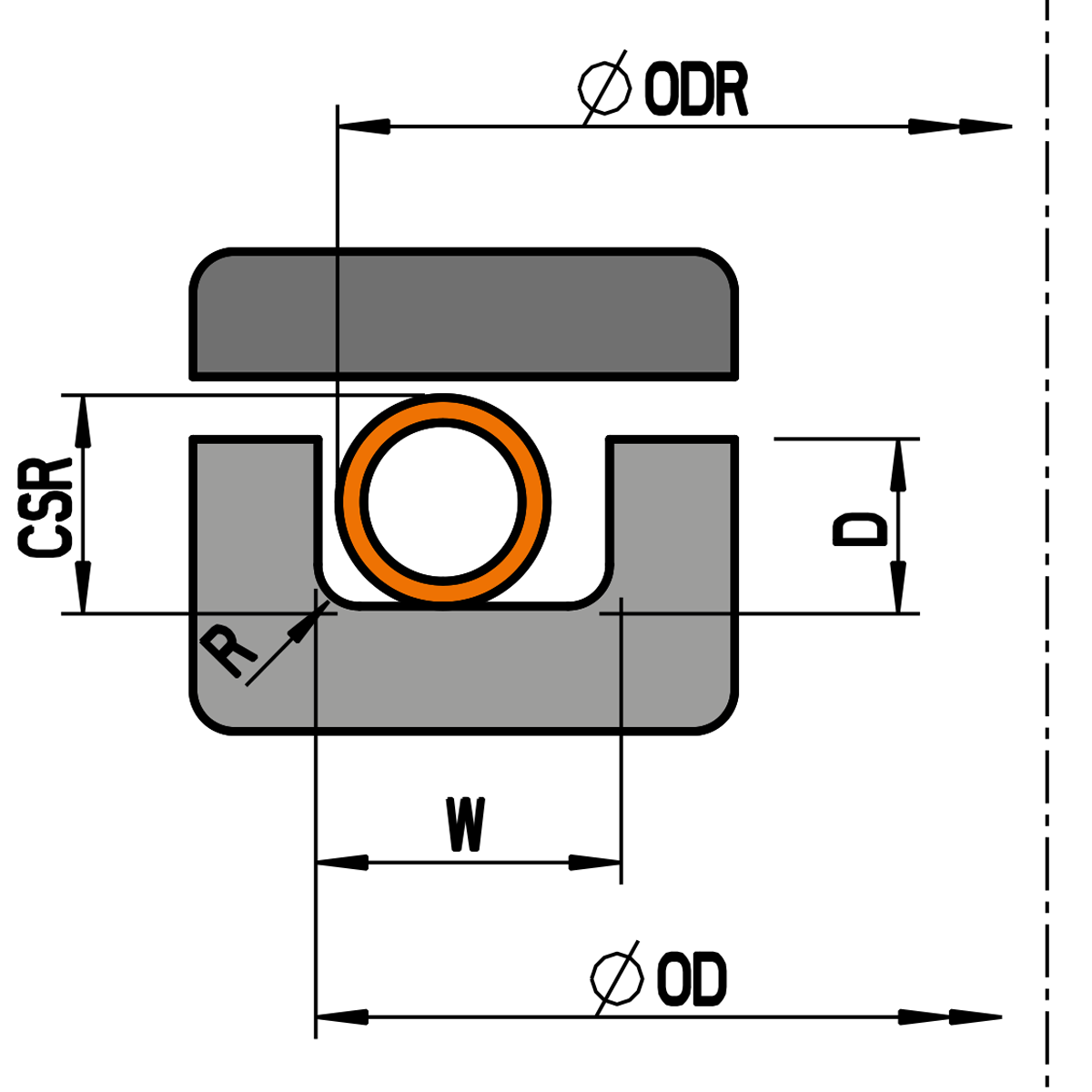
For internal pressure applications the outer diameter of the ring ODR is calculated as follows:
ODR = OD - Z
External pressure application
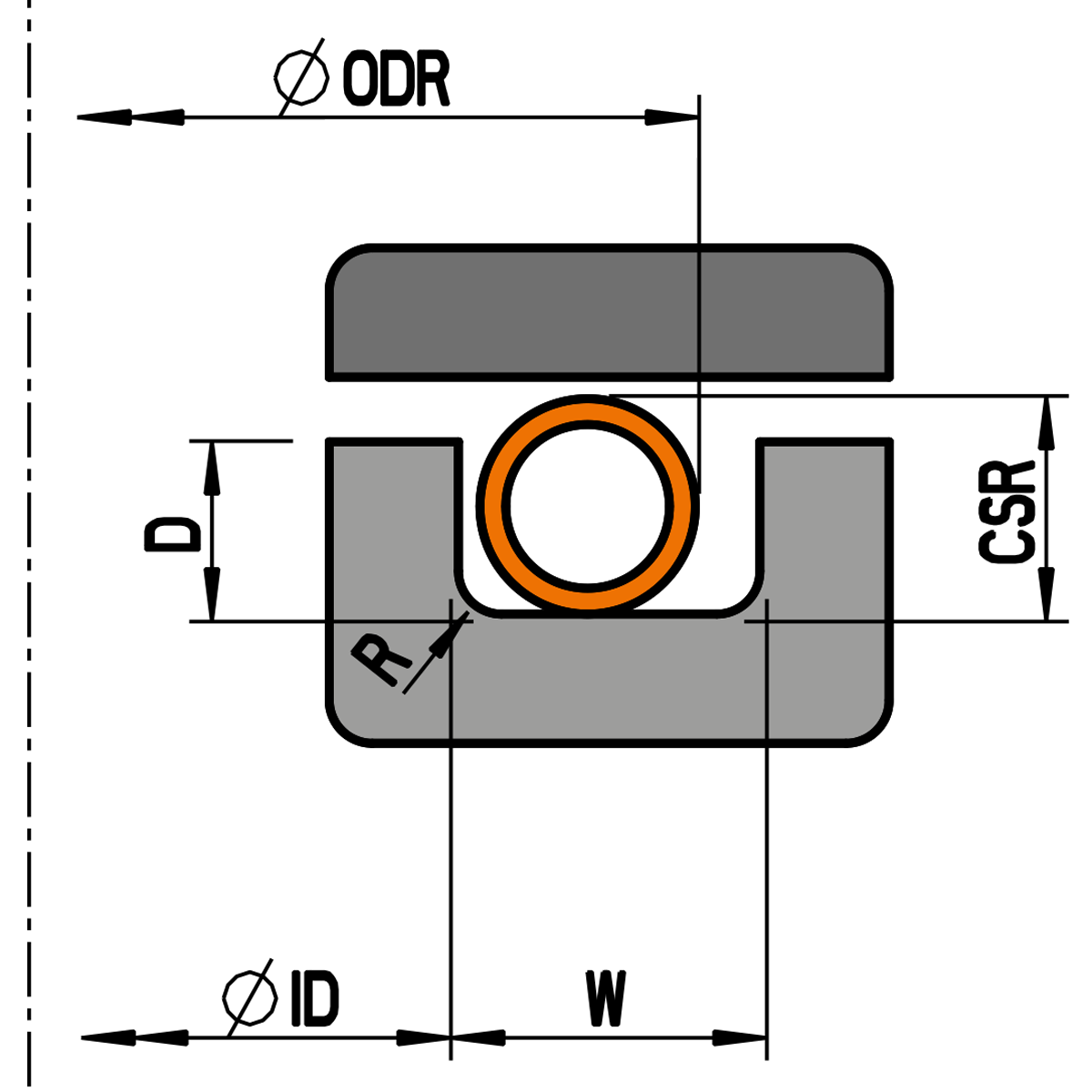
For external pressure applications the outer diameter of the ring ODR is calculated as follows:
ODR = ID + Z + 2*CSR + (4*Pt)
(4*Pt) only valid for rings with coating For the calculation, the largest value of the selected value range must be used.
| CSR | Nominal cross-section: cross-sectional dimension (without coating) e.g. similar to the cord thickness of elastomer O-rings |
|---|---|
| Code | Performance Index: shows characteristics of the ring (e.g. pressing load, springback) |
| D | Groove depth: axial design dimension to which the ring is pressed from the original cross-section CSR. |
| F | Pressing load: the mentioned guide values refer to 1mm seal length. To obtain the total load of the seal for the design of the construction, this value must be multiplied by the circumferential length of the seal. |
| ID | Inner diameter of the groove: reference dimension for external pressure applications. |
| OD | Outside diameter of groove: reference dimension for internal pressure applications. |
| ODR min. | Outside diameter of the ring: The outside diameter of the ring is freely selectable from the mentioned minimum dimension ODR min. and is at the same time the corresponding dimension to the outside or inside diameter of the groove. |
| Pt | coating thickness |
| R | Radius: Design dimension that improves the support of the ring under pressure |
| SB | Springback: maximum possible measure by which the ring can spring back elastically overall. Important value in connection with possible flange gaps. |
| Wmin | groove width: radial design minimum dimension. The specified minimum dimension Wmin. must not be undercut. |
| Wt | Wall thickness: sheet thickness of the ring. |
| Z | diametric clearance between ring and groove. |
The following ordering example describes a metal O-ring in
(suitable for groove outer diameter OD 55.00mm)
Configure MOR
for internal pressure
Configure MOR
for external pressure
| Metal O-Ring MOR | Installation space | Performance | ||||||||
|---|---|---|---|---|---|---|---|---|---|---|
| Nominal cross-section |
Performance index |
Wall thickness | Outer diameter ring |
diametrical clearance |
Groove depth | Groove width | Radius | Pressing load (Guide values) |
Springback (Guide values) |
|
| CSR mm |
Code | Wt mm |
Ø ODR min. mm |
Z mm |
D mm |
Tol. mm |
W min. mm |
R max. mm |
F ca. N/mm |
SB ca. mm |
| 0,89 | w | 0,15 | 6 | 0,20 | 0,65 | +0,05 | 1,40 | 0,25 | 70 | 0,01 |
| 1,19 | w | 0,20 | 10 | 0,25 | 0,95 | +0,05 | 1,80 | 0,30 | 80 | 0,02 |
| 1,57 | w | 0,25 | 15 | 0,25 | 1,15 | +0,10 | 2,30 | 0,35 | 110 | 0,03 |
| 1,57 | s | 0,36 | 15 | 0,25 | 1,15 | +0,10 | 2,30 | 0,35 | 230 | 0,03 |
| 2,39 | w | 0,25 | 25 | 0,30 | 1,90 | +0,10 | 3,20 | 0,50 | 60 | 0,05 |
| 2,39 | s | 0,46 | 25 | 0,30 | 1,90 | +0,10 | 3,20 | 0,50 | 210 | 0,03 |
| 3,18 | w | 0,25 | 45 | 0,40 | 2,55 | +0,10 | 4,20 | 0,75 | 40 | 0,07 |
| 3,18 | s | 0,51 | 45 | 0,40 | 2,55 | +0,10 | 4,20 | 0,75 | 170 | 0,04 |
| 3,96 | w | 0,51 | 70 | 0,60 | 3,20 | +0,10 | 5,20 | 1,25 | 115 | 0,08 |
| 3,96 | s | 0,64 | 70 | 0,60 | 3,20 | +0,10 | 5,20 | 1,25 | 195 | 0,06 |
| 4,78 | w | 0,51 | 100 | 0,70 | 3,85 | +0,15 | 6,40 | 1,30 | 95 | 0,10 |
| 4,78 | s | 0,64 | 100 | 0,70 | 3,85 | +0,15 | 6,40 | 1,30 | 160 | 0,08 |
| 6,35 | w | 0,64 | 160 | 0,75 | 5,05 | +0,20 | 8,50 | 1,50 | 110 | 0,15 |
| 6,35 | s | 0,81 | 160 | 0,75 | 5,05 | +0,20 | 8,50 | 1,50 | 190 | 0,10 |
| 9,53 | w | 0,97 | 300 | 1,00 | 8,20 | +0,30 | 12,70 | 1,50 | 170 | 0,15 |
| 9,53 | s | 1,24 | 300 | 1,00 | 8,20 | +0,30 | 12,70 | 1,50 | 290 | 0,12 |
| 12,7 | w | 1,27 | 800 | 1,25 | 11,10 | +0,30 | 16,50 | 1,50 | 200 | 0,20 |
| 12,7 | s | 1,65 | 800 | 1,25 | 11,10 | +0,30 | 16,50 | 1,50 | 370 | 0,18 |
Mentioned performance guide values are valid for seals made from Inconel X-750 work hardened.
Preferred sizes are shown in bold. Other sizes not listed in table available on request.
Ring material
| Ring material | Code | Material no. |
|---|---|---|
| SS321 | 3 | 1.4541 |
| Inconel 600 | 4 | 2.4816 |
| Inconel X-750 | 5 | 2.4669 |
Other materials on request.
Design
| Design | Code |
|---|---|
| normal | NP |
| self-energizing inside | SI |
| self-energizing outside | SO |
| pressure filled | PF |
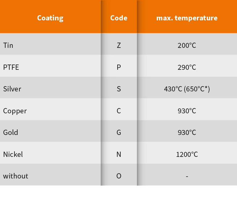
Coating
| Coating | Code | max. temperature |
|---|---|---|
| Tin | Z | 200°C |
| PTFE | P | 290°C |
| Silver | S | 430°C (650°C*) |
| Copper | C | 930°C |
| Gold | G | 930°C |
| Nickel | N | 1200°C |
| without | O | – |
* Only valid for non-oxidizing media.
Other materials on request.
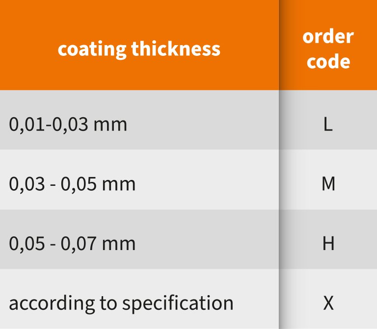
Coating thickness
| Coating thickness Pt | Code |
|---|---|
| 0,01 - 0,03 mm | L |
| 0,03 - 0,05 mm | M |
| 0,05 - 0,07 mm | H |
Other coating thicknesses on request.
Metal C-Rings
Metal U-Rings
Customized designs
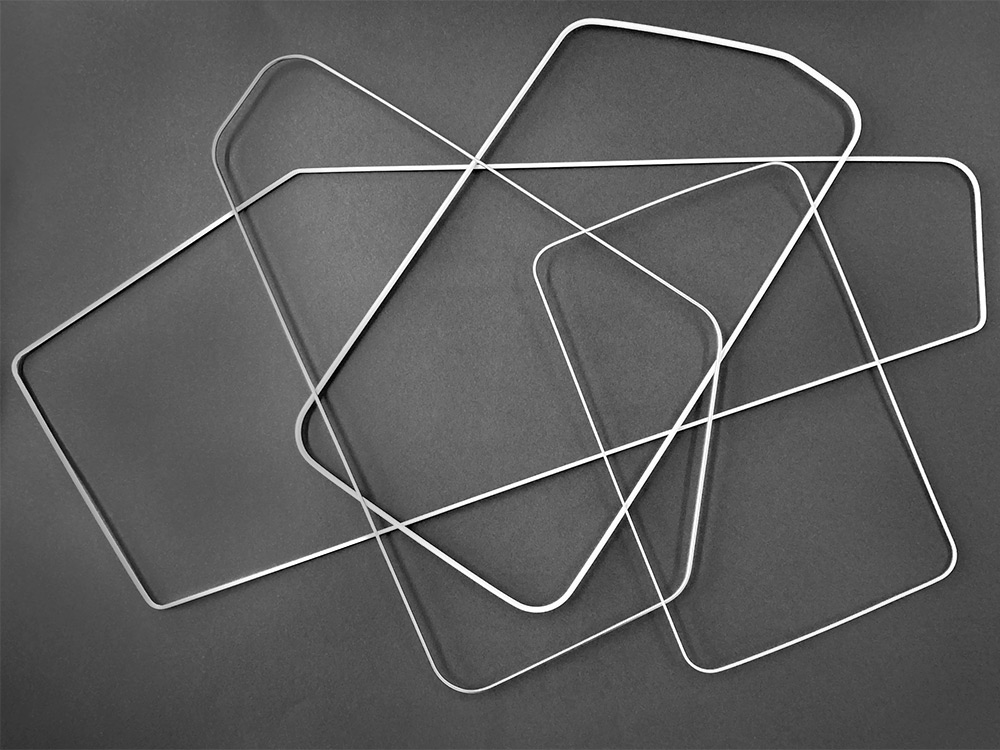
In addition to the circular version, many of the seal types listed in the catalog are also available as shaped and segment seals for a wide variety of applications.
The minimum radii that can be implemented are based on the minimum diameters specified in the table for the respective type and are formed from ODRmin/2 for internal pressure applications, IDRmin/2 applies for external pressure applications.
A detailed representation of the groove contour incl. dimensioning and tol. with reference to internal or external pressure application is required for the assessment of feasibility.
Hot Runner seals
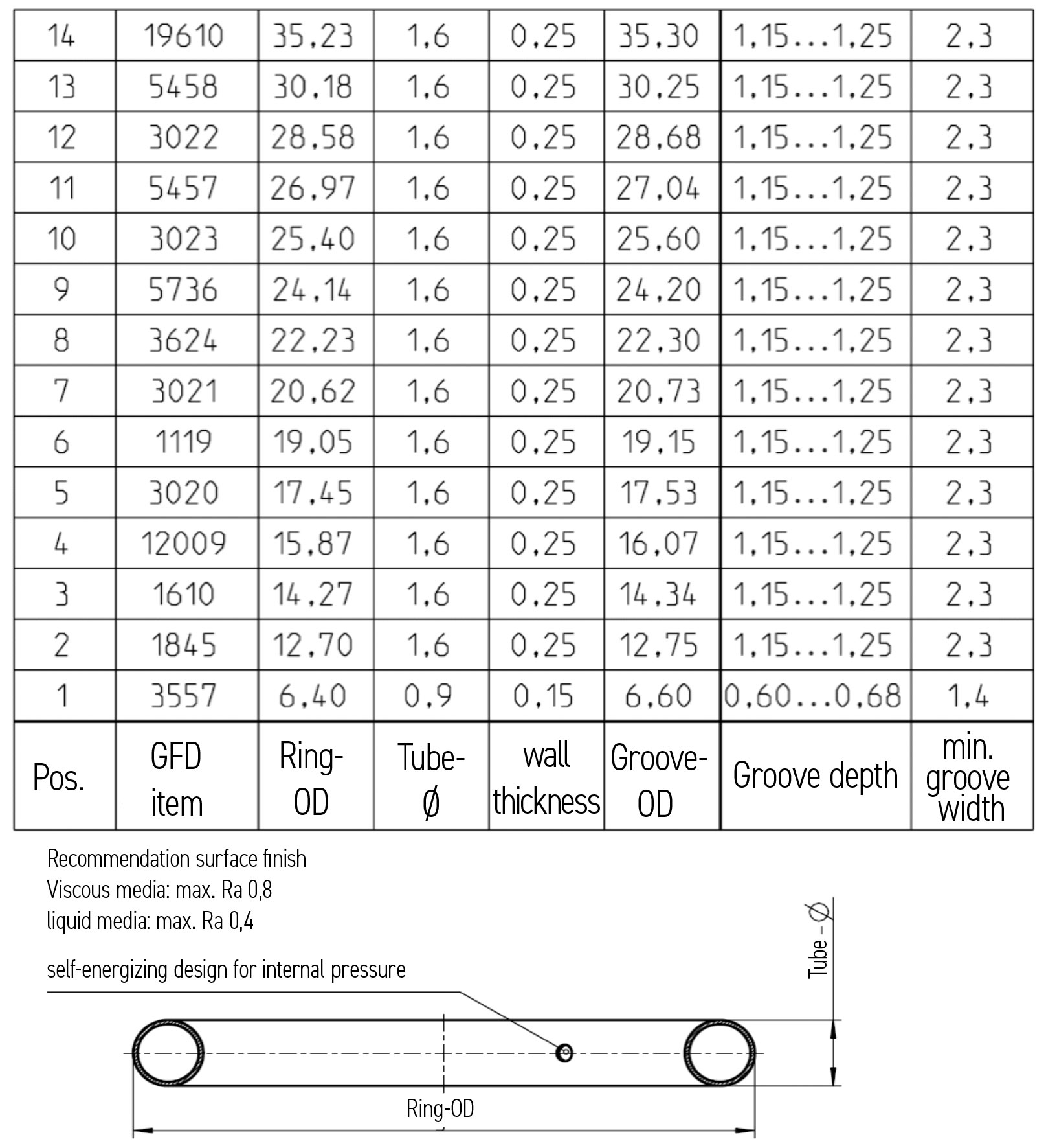
Metal O-rings in hot runner systems of plastic injection molding machines
Seals for hot runner systems are available from stock in many sizes, as the groove dimensions from different manufacturers are often identical.
The seals are used, for example, in the nozzles, connectors and component separations of HK systems.
The seal is a " one-time " item and is exchanged when the components are changed.
Space Limiter
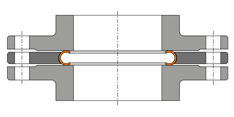
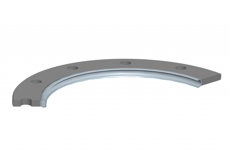
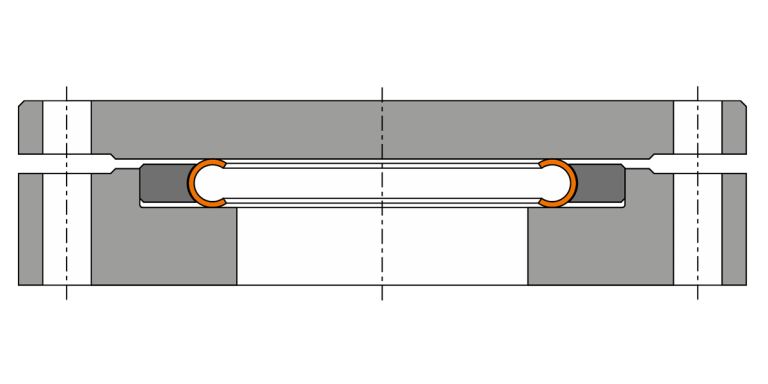
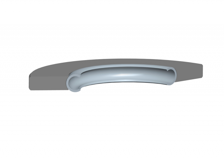
The Space Limiter enables the use of resilient metal seals when there is no groove geometry between two flanges. It limits the compression of the gasket to the required height and supports the seal when pressurized.
The surface finish of the flange pairs in the area of the counter sealing surface should follow GFD recommendations.
Space Limiters can be designed, for example, with a bolt circle corresponding to that of the bolted connections of the flanges.
If there is a shoulder in the flange connection, this can be used as a form fit.
Space Limiters can be manufactured for both internal and external pressure. A detailed flange drawing incl. dimensions and tol. with reference to internal or external pressure application is required for checking feasibility.


